The ATtiny3224 microcontroller Is a member of the latest series of microcontrollers from Microchip Technology Inc. The ATtiny3224 utilizes an AVR® architecture running up to 20 MHz with 32 KB program flash memory in a 14 pin SOIC package. This new series chip, with its increased memory capacity of 32 KB of flash, equals the flash memory capacity of the famous ATmega328P, the core of the Arduino UNO.
In addition to its common AVR® architecture and program flash memory size, this microcontroller can be programmed directly from the Arduino IDE. Not bad for a less than 1 dollar stand alone microcontroller. For all the details on the ATtiny3224, see the datasheet on the manufacturer’s website.
This article will explore the new ATtiny3224, including how to mount it on a prototype breadboard. This article will also document the construction of a simple programmer to allow you to program the ATtiny3224 with the Arduino IDE and load many of the well known Arduino sketches. This article assumes some prior experience with the Arduino and Arduino IDE. If you have never worked with the Arduino, I recommend getting an Arduino UNO and downloading the free IDE to get familiar with the platform.
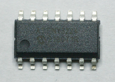
First, let’s take a look at the ATtiny3224. The chip comes in a 14 pin SOIC package. This, unfortunately for many hobbyists, is not a through hole DIP. The new chip is a surface mount device, or SMD. Like virtually all new chips, these new microcontrollers are not available in the DIP format. Fear not. Our first step is to take the chip and make it capable of mounting like a DIP.
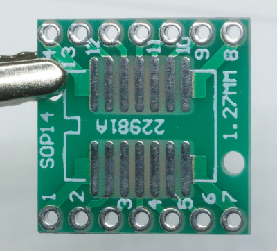
We will accomplish this with a SOIC to DIP adapter board. Adapter boards are readily available in various sizes on Amazon and eBay. You mount the SMD device to the top of the board and then solder male headers to both edges. Once populated, the adapter board can be mounted like a DIP on a prototype breadboard, perf board, or a through hole PCB.
There are two methods to solder SMD devices to an adapter board. The first, or traditional method, is with solder paste and a hot air soldering station. The second, is to use a conventional pencil soldering iron with a flat tip and ample flux. I strongly suggest taking a look at YouTube for the many examples of both techniques of soldering SMD devices. Fortunately, a 14 pin SOIC chip has relatively wide lead spacing making both techniques possible. In fact, the 0.05” lead spacing is only half of the 0.1” lead spacing on a similar DIP.
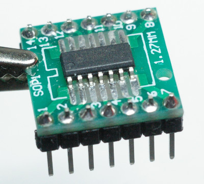
I use the traditional method. First, thoroughly clean the pads on the adapter board with 90%+ isopropyl alcohol and then carefully place solder paste with a small device like a toothpick on each of the pads. Place the chip on the adapter carefully centering the device and aligning each lead on each pad. Once the chip is placed on the pad, wave the hot air on each side until the solder paste flows. If you are unsure of what temperature to set the hot air soldering station, first read the documentation on the soldering paste. Second, there is nothing preventing you from slowly turning up the temperature until the solder flows. Just be sure to let the chip cool down in between each attempt. After the solder flows, inspect carefully to ensure there are no bridges between the leads. If there are, this can can be fixed with a pencil soldering iron with a thin tip and soldering wick or a solder sucker. Once your are satisfied that the ATtiny3224 is mounted properly on the adapter board, solder two 7 pin headers to each side of the adapter with a pencil soldering iron.
The next step is to download and install the Arduino IDE and configure it with a new core to provide programming support for the ATtiny3224. At the time of this writing, I am using Arduino IDE version 1.8.19. The Arduino support for all tinyAVR 0/1/2-series including the new ATtiny3224 will be provided by the megaTinyCore developed by Spence Konde. I strongly recommend reading his repository on github.com.
To perform a Boards Manager Installation of the megaTinyCore on the Arduino IDE, follow the following instructions from Spence Konde:
In the Arduino IDE, navigate to File -> Preferences, and add the following URL to the space following “Additional Boards Manager URLs”:
http://drazzy.com/package_drazzy.com_index.json
Then navigate to Tools -> Boards -> Boards Manager
Wait while the list loads (takes longer than one would expect, and refreshes several times). Select “megaTinyCore by Spence Konde” and click “Install”. For best results, choose the most recent version.
We will now proceed with building the UDPI programmer from a common USB to TTL module. UDPI is a single wire programming protocol developed by Microchip Technology Inc. The acronym stands for Unified Program and Debug Interface. For this example, I will be using a USB to TTL module purchased from Amazon.
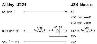
I chose this particular USB to TTL module because it is based on the CH340 and already has an internal 1.5k Ω resistor in series with TXD. The only additional components are a Shockley diode and a 470 Ω resistor. Here is a schematic of the programmer.
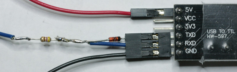
Above is the completed programmer. The Shockley diode is across the TXD and RXD pins and the 470 Ω resistor is in series forming the blue UDPI programming wire. This photo was taken just before applying shrink wrap over the blue wire and two components. The blue UDPI programming wire connects directly to pin 10 on the ATtiny3224. The red 5V and black ground wires supply power to the ATtiny3224 during programming. Always verify that the internal resistor on the TXD pin is 1.5k Ω. If you are using a different USB to TTL module, and the internal resistor’s value is different from 1.5k Ω, you will need to rethink the component values of the programmer. Spence Konde also has some suggestions on using various USB to TTL modules.
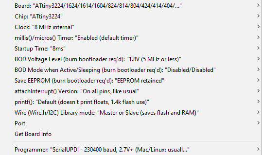
Our final step is to program an ATtiny3224 microcontroller from the Arduino IDE using our new UDPI programmer. Navigate to Tools -> Board: -> megaTinyCore and select “ATtiny3224/1624/ …”. Then navigate to Chip: and select ATtiny3224. I leave most of the settings at their defaults. I set the Clock: to 8MHz internal. You can try a faster clock speed (which requires more power) if necessary for your application. For the programmer, select “SerialUDPI – 230400 baud, 2.7V+ (Mac/Linux …” The following screen shot shows the working setting that I generally use.
Now that the Arduino IDE is configured for programming an ATtiny3224, connect your programmer to the microcontroller, blue UDPI programming line to pin 10, and power to pins 0 and 14. Connect the programmer to your computers USB, check that you are using the correct USB port, load a familiar sketch into the Arduino IDE, and click Upload. I found that a USB extension cable facilitates connecting the programmer to your computer.
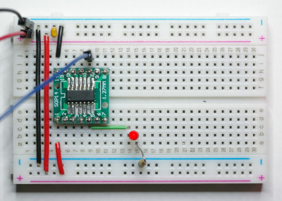
Here we have the familiar Arduino blink sketch running on the ATtiny3224. The green wire is from physical pin 5 to the LED. In the sketch, you will be using logical pin 3. The only other components are the 470 Ω current limiting resistor for the LED and a 100nF decoupling capacitor across the power rail. There are 11 usable I/O pins on the ATtiny3224, physical to logical pin mappings for the remaining pins are 2->0, 3->1, 4->2, 6->4, 7->5, 8->6, 9->7, 11->8, 12->9, and 13->10
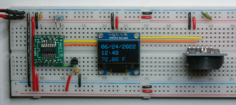
A final example of the ATtiny3224 with a more complex sketch reading data from an analog temperature sensor and a real time clock and reporting the results on an OLED display. The analog temperature sensor is wired to physical pin 5, same as the blink sketch. The OLED and real time clock are connected to the microcontroller over a common I²C buss. The ATtiny3224 utilizes physical pins 8 and 9 for the SDA and SCL I²C lines. Power in this case is provided directly from a power supply. Once programmed, you can run the ATtiny3224 with any voltage it and the supporting devices are specified. The ATtiny3224 is rated to be powered between 1.8V and 5.5V.